Arduino Uno R3: The Classic Microcontroller for Makers
The Arduino Uno R3 is a versatile and beginner-friendly microcontroller board, ideal for learning electronics and prototyping.
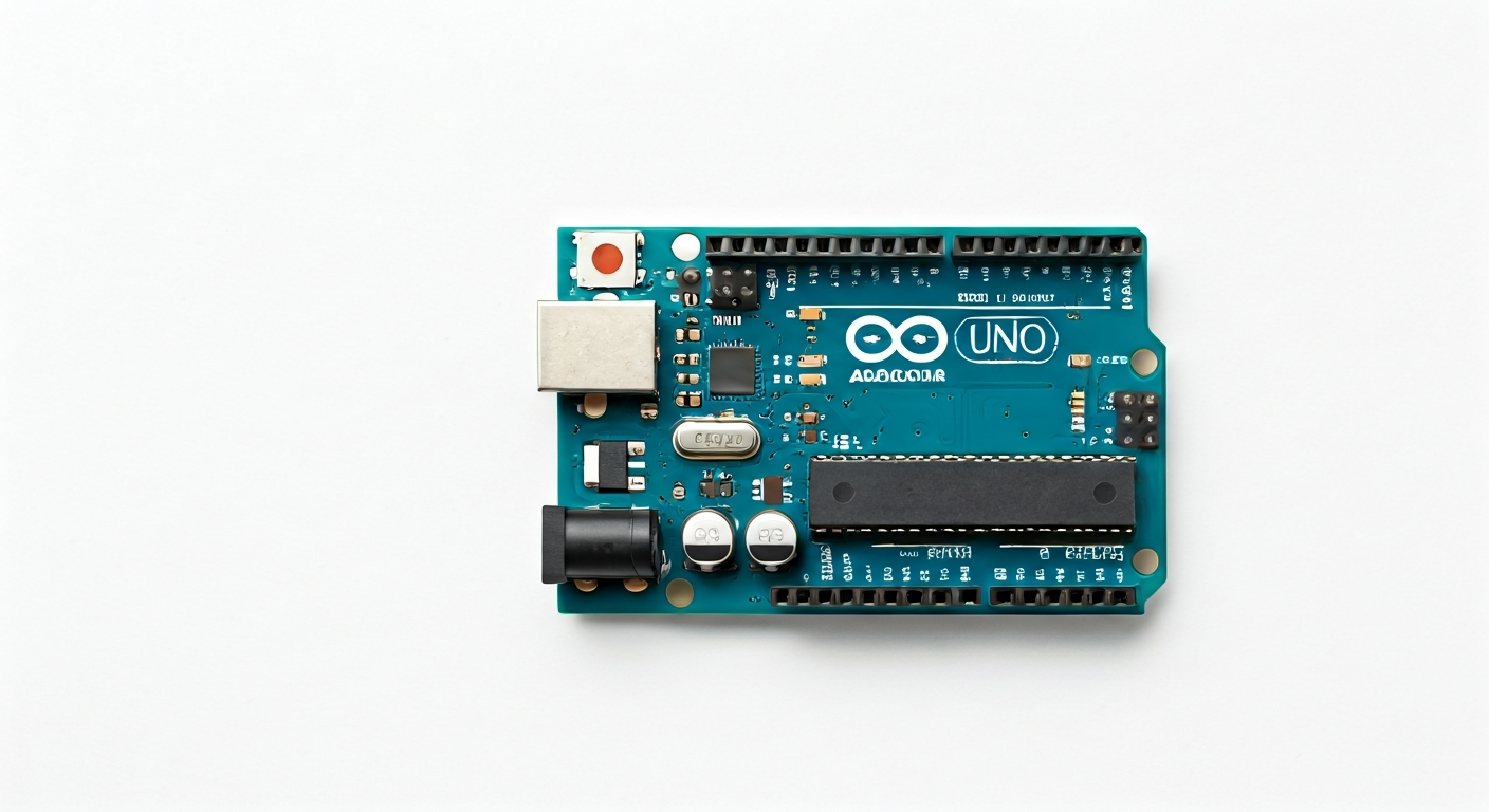
The Arduino Uno R3 is the fifth and current revision of the Arduino Uno board, a widely adopted microcontroller platform designed for ease of use and accessibility. Released in 2011, it builds upon the legacy of its predecessors, offering a robust and reliable foundation for countless electronic projects. The Uno R3 is part of the Arduino family, known for its open-source hardware and software philosophy, which fosters a large and active community.
At the heart of the Arduino Uno R3 lies the ATmega328P microcontroller, an 8-bit AVR RISC architecture chip manufactured by Microchip Technology. This microcontroller provides a good balance of processing power, memory, and peripheral capabilities for a wide range of applications. Its straightforward architecture and extensive documentation make it an excellent choice for those new to embedded systems.
The Uno R3 maintains the familiar form factor and pinout of previous Uno versions, ensuring compatibility with existing shields and accessories. It sits as a foundational board in the Arduino ecosystem, offering a solid entry point before users might explore more advanced boards with greater processing power, memory, or specialized features. Its enduring popularity is a testament to its simplicity, extensive library support, and the vast amount of learning resources available.
This board is particularly suited for students, hobbyists, and makers who are embarking on their first microcontroller projects. Whether it's blinking an LED, reading sensor data, controlling motors, or building interactive art installations, the Uno R3 provides the necessary tools and a gentle learning curve. Its 5V operating logic also simplifies interfacing with many common electronic components.
Specifications
| Microcontroller / SoC | ATmega328P |
| Architecture | 8-bit AVR RISC |
| Clock speed | 16 MHz |
| Flash / Storage | 32 KB (ATmega328P) |
| RAM / SRAM | 2 KB (ATmega328P) |
| EEPROM | 1 KB (ATmega328P) |
| Operating voltage | 5V |
| Digital I/O pins | 14 (6 with PWM output) |
| Analog / ADC | 6 analog input pins (10-bit resolution) |
| PWM | 6 pins (3, 5, 6, 9, 10, 11) |
| Connectivity | UART, SPI, I2C |
| USB | ATmega16U2 (for USB-to-serial communication) |
| Power input | 7-12V recommended DC barrel jack or VIN pin, 5V via USB |
| Dimensions | 68.6mm x 53.4mm |
Pinout & pin functions
| Pin | Function |
|---|---|
| 5V | Power supply output (regulated 5V) |
| 3.3V | Power supply output (regulated 3.3V from onboard regulator) |
| GND | Ground |
| GND | Ground |
| IOREF | Voltage Reference for the I/O pins |
| RESET | Resets the microcontroller |
| 0 (RX) | Serial Receive pin (UART) |
| 1 (TX) | Serial Transmit pin (UART) |
| 2 | General purpose digital I/O |
| 3 | Digital I/O, PWM output |
| 4 | General purpose digital I/O |
| 5 | Digital I/O, PWM output |
| 6 | Digital I/O, PWM output |
| 7 | General purpose digital I/O |
| 8 | General purpose digital I/O |
| 9 | Digital I/O, PWM output |
| 10 (SS) | Digital I/O, SPI Slave Select |
| 11 (MOSI) | Digital I/O, SPI Master Out Slave In |
| 12 (MISO) | Digital I/O, SPI Master In Slave Out |
| 13 (SCK) | Digital I/O, SPI Serial Clock |
| A0 | Analog Input pin, Digital I/O |
| A1 | Analog Input pin, Digital I/O |
| A2 | Analog Input pin, Digital I/O |
| A3 | Analog Input pin, Digital I/O |
| A4 (SDA) | Analog Input pin, Digital I/O, I2C Data |
| A5 (SCL) | Analog Input pin, Digital I/O, I2C Clock |
| AREF | Analog Reference Voltage |
| VIN | Power input (7-12V recommended) |
Wiring & circuit basics
Powering the Arduino Uno R3 can be done through its USB port (providing 5V and sufficient current for many projects) or via the DC barrel jack or VIN pin. When using the barrel jack or VIN pin, a voltage between 7V and 12V is recommended. The board has an onboard voltage regulator that steps this down to the 5V required by the ATmega328P and other 5V components. Avoid supplying more than 12V to prevent overheating the regulator, and ensure your power source can supply at least 500mA for stable operation, especially when powering external devices.
The Arduino Uno R3 operates at 5V logic levels. This means that a HIGH digital signal is approximately 5V, and a LOW signal is 0V. When interfacing with components that require 3.3V logic (like some sensors or microcontrollers), a logic level converter is necessary to prevent damage. Conversely, 5V-compatible components can typically be connected directly. Always ensure you connect your grounds together when linking multiple devices to the Arduino to establish a common reference point.
A simple example circuit is connecting an LED. Connect the longer leg (anode) of the LED to a digital pin (e.g., pin 13). Connect the shorter leg (cathode) to one end of a current-limiting resistor (typically 220-330 Ohms for a standard LED). Connect the other end of the resistor to a GND pin on the Arduino. This setup prevents excessive current from flowing through the LED and damaging it or the Arduino pin. The resistor value can be calculated based on the LED's forward voltage and desired current.
Programming & getting started
The most common toolchain for the Arduino Uno R3 is the Arduino IDE (Integrated Development Environment), available for Windows, macOS, and Linux. It provides a simple editor, a compiler, and an uploader. To get started, download and install the IDE from the official Arduino website. Connect your Uno R3 to your computer via USB. Select the correct board (Arduino Uno) and COM port from the Tools menu in the IDE. You can then write code in C/C++ (using the Arduino framework), verify it, and upload it to the board by clicking the Upload button. Many libraries are available to simplify interaction with sensors and modules.
For more advanced users or those preferring different workflows, PlatformIO is a popular alternative that integrates with various IDEs (like VS Code) and offers robust build management and library handling. MicroPython and CircuitPython are also options, though they typically require a bootloader to be flashed first and offer a Python-based programming experience, which can be faster for prototyping but might have performance limitations compared to C/C++ for highly demanding tasks on the ATmega328P.